Building a Speedometer with Compose Canvas API
The other day, while sitting in the back of a taxi, I noticed the speedometer and had the idea to build one using Jetpack Compose (because, why not? 😛). In this post, I will explain the process of building the speedometer and discuss the challenges I faced. This post assumes a basic knowledge of the Canvas API in Jetpack Compose.
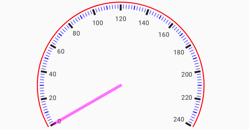
The speedometer we are building will look like the one above.
The Canvas and Drawing the Arc
To bring our vision of the speedometer to life, we leverage the powerful Canvas API in Jetpack Compose. This API empowers us to create, manipulate, and render shapes, lines, and text directly onto the screen, endowing us with precise control over the speedometer’s visual representation.
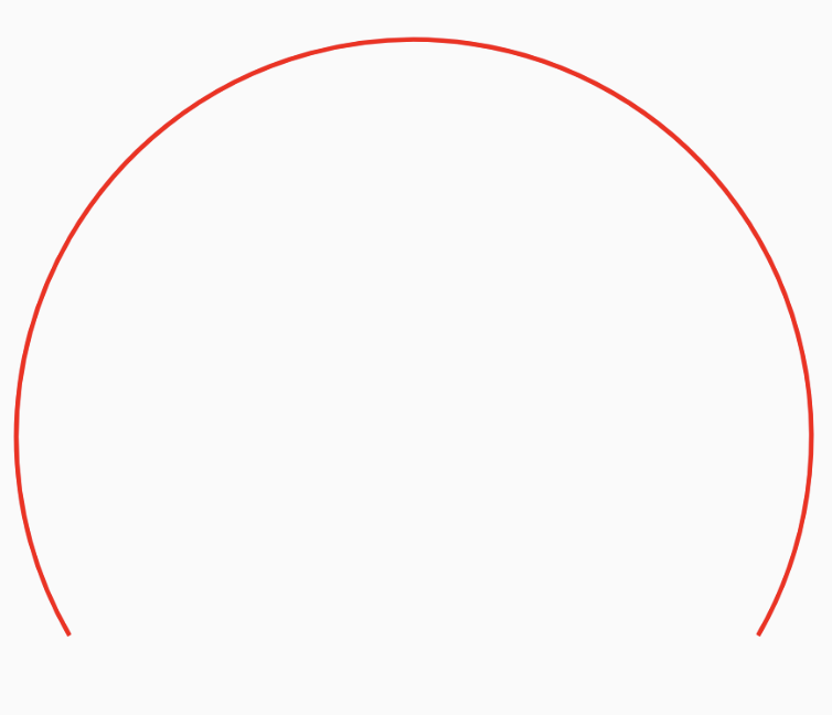
Once we have access to the Canvas, we will use the drawArc function to draw the semicircular arc that represents the speed range. This function requires several parameters, including the start angle and sweep angle, both measured in degrees. In our speedometer, we set the start angle to 30 degrees, which corresponds to the starting point of the speedometer arc.
For
drawArc, It starts fromstartAngledegrees (with zero degrees being 3 o’clock), drawing up clockwise to thesweepAnglerelative to the startAngle.
For the sweep angle, we opt for -240 degrees. A negative value in this context signifies a counterclockwise sweep. This choice produces a semicircular arc spanning from 30 degrees to 270 degrees, encompassing a 240-degree arc, thereby crafting the characteristic shape of the speedometer.
1
2
3
4
5
6
7
8
9
10
11
val modifier = Modifier.padding(90.dp).requiredSize(360.dp)

Canvas(modifier = modifier, onDraw = {
	// Draw the speedometer arc
  drawArc(
      color = Color.Red,
      startAngle = 30f,
      sweepAngle = -240f,
      useCenter = false,
      style = Stroke(width = 2.0.dp.toPx())
  )
Drawing the SpeedMarkers
The markers are divided into three types: major, minor, and small indicators. Major indicators represent significant speed intervals (multiples of 20) and are drawn using a thick line to emphasise their importance. Minor indicators represent intermediate speed intervals (multiples of 10) and are drawn using a medium-sized line. Small indicators are used to fill in the gaps between major and minor indicators (multiples of 2) and are drawn with a thin line.
The Mathematics Behind Marker Placement
To draw a the marker line using the drawLine method, we need to provide a startPoint and an endPoint. In order to determine the startPoint on the arc (i.e., where the line starts), we can use trigonometry (remember middle school math?). Here’s how we can calculate the point on a circle:
- Determine the angle at which we want to place the point on the circle. This angle is measured in degrees.
Use the following function to calculate the coordinates of the point:
1
2
3
4
5
6
7
8
9
10
11
 private fun pointOnCircle(
     thetaInDegrees: Double,
     radius: Float,
     cX: Float,
     cY: Float,
 ): Offset {
     val x = cX + (radius * sin(Math.toRadians(thetaInDegrees)).toFloat())
     val y = cY + (radius * cos(Math.toRadians(thetaInDegrees)).toFloat())

     return Offset(x, y)
 }
xandyare the coordinates of the point on the circle.cXandcYare the coordinates of the center of the circle.radiusis the radius of the circle.- The angle converted to radians using the formula:
thetaInRadians = Math.toRadians(thetaInDegrees)
Similarly, we can calculate the endPoint by adjusting the radius of the circle based on the length of the marker we are drawing. Finally, we can connect the startPoint and endPoint using the drawLine method to draw the marker line.
Marker
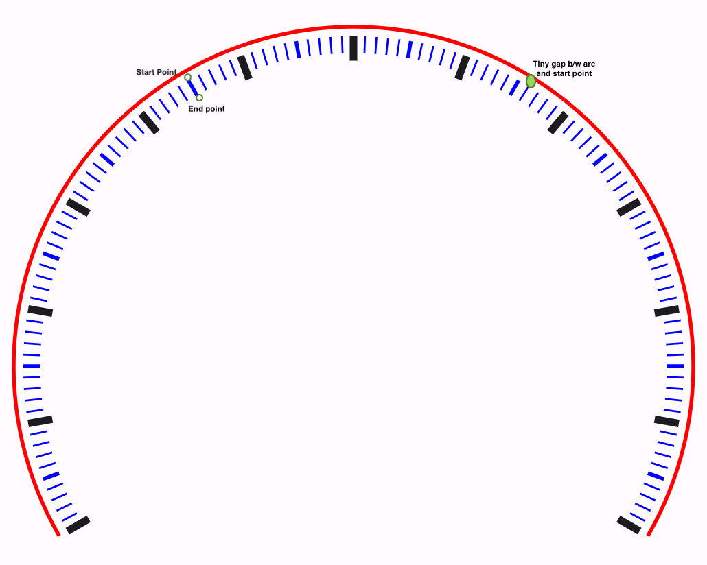
To draw the markers, we start counting down from 300 to 0 in steps of 2, following the small indicator as defined above. Each of the marker indicators is then drawn.
Here is the relevant code snippet (note the use of INDICATOR_INITIAL_OFFSET to create a small gap between the arc and the marker start point, as shown in the screenshot below):
1
2
3
4
5
6
7
8
9
10
11
12
13
14
15
16
17
18
19
20
21
22
23
24
25
26
27
28
29
30
31
32
33
34
35
36
37
38
39
40
41
42
43
44
45
46
47
48
49
50
51
52
53
54
55
56
for (angle in 300 downTo 60 step 2) {
    val speed = 300 - angle

    val startOffset = pointOnCircle(
        thetaInDegrees = angle.toDouble(),
        // Offset from the center to start drawing the markers
        radius = size.height / 2 - INDICATOR_INITIAL_OFFSET.dp.toPx(),
        cX = center.x,
        cY = center.y
    )

    if (speed % 20 == 0) {
        // Major indicator marker
        val endOffset = pointOnCircle(
            thetaInDegrees = angle.toDouble(),
            // Length of major indicator
            radius = size.height / 2 - MAJOR_INDICATOR_LENGTH.toPx(),
            cX = center.x,
            cY = center.y
        )
        // Draw the major indicator marker using a thick line
        speedMarker(startOffset, endOffset, SolidColor(Color.Black), 4.dp.toPx())
    } else if (speed % 10 == 0) {
        // Minor indicator marker
        val endOffset = pointOnCircle(
            thetaInDegrees = angle.toDouble(),
            // Length of minor indicator
            radius = size.height / 2 - INDICATOR_LENGTH.toPx(),
            cX = center.x,
            cY = center.y
        )
        // Draw the minor indicator marker using a medium-sized line
        speedMarker(startOffset, endOffset, SolidColor(Color.Blue), 2.dp.toPx())
    } else {
        // Small indicator marker
        val endOffset = pointOnCircle(
            thetaInDegrees = angle.toDouble(),
            // Length of small indicator
            radius = size.height / 2 - INDICATOR_LENGTH.toPx(),
            cX = center.x,
            cY = center.y
        )
        // Draw the small indicator marker using a thin line
        speedMarker(startOffset, endOffset, SolidColor(Color.Blue), 1.dp.toPx())
    }
}

private fun DrawScope.speedMarker(
    startPoint: Offset,
    endPoint: Offset,
    brush: Brush,
    strokeWidth: Float
) {
    drawLine(brush = brush, start = startPoint,
    end = endPoint, strokeWidth = strokeWidth)
}
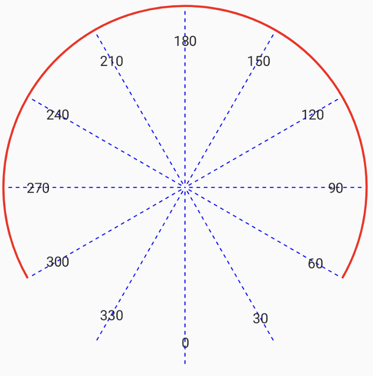
Notably, there’s an apparent disparity between the start and sweep angles when drawing the arc (30 and -240 degrees) and the angles used for marking and speed representation (300 to 60 degrees).
In the drawArc function, the start angle is determined by measuring the angle from the center of the circle to the intersection point with the 3 o’clock position. However, when we come to placing the markers on the speedometer, we consider the entire circular context to which the speedometer arc belongs. In this context, we find that the arc begins at 300 degrees and ends at 60 degrees, where 300 degrees corresponds to 0 speed, and 60 degrees signifies the maximum speed (in this case, 240).
Drawing the speed text
Each major indicator on the speedometer is associated with a speed value. To display the speed text uniformly along the arc, we will again use the pointOnCircle method again to determine the starting point for the text.
1
2
3
4
5
6
7
8
9
10
11
12
13
14
15
16
17
18
val textOffset = pointOnCircle(
        thetaInDegrees = textAngle,
        radius = size.height / 2 - MAJOR_INDICATOR_LENGTH.toPx()
 - INDICATOR_INITIAL_OFFSET.toPx(),
        cX = center.x,
        cY = center.y
    )

drawContext.canvas.save()
drawContext.canvas.translate(
    textOffset.x,
    textOffset.y
)

// Draw the speed text at the calculated position and angle
drawText(textLayoutResult)

drawContext.canvas.restore()
Now that we have calculated the position of the speed text, we can proceed to draw it on the canvas. Before applying any transformations (such as translations or rotations), we save the current state of the canvas using the drawContext.canvas.save() function. This ensures that we can restore the canvas to its original state after drawing the text.
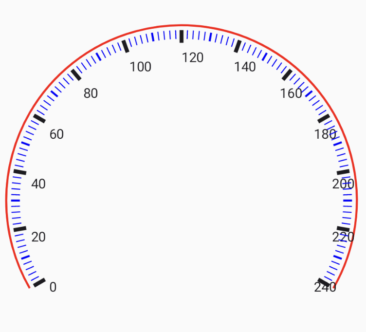
Here, the text is not properly aligned with the markers, and the spacing between the marker and text is inconsistent across the speedometer. This is because the point on the circle is being calculated based on the start of the text. Instead, we should use the center of the text’s width as the reference point. The width of the text changes based on the speed, whether it is a single digit, double digit, or triple digit. To address this, we can use the TextMeasurer to obtain the width of the text and factor it into our calculation.
1
2
3
4
5
6
7
8
9
10
11
12
13
14
15
16
17
18
19
20
21
22
23
24
val textLayoutResult = textMeasurer.measure(speed.toString())

val textWidth = textLayoutResult.width
val textHeight = textLayoutResult.size.height
val textOffset = pointOnCircle(
        thetaInDegrees = textAngle,
        // Adjusting radius with text width
        radius = size.height / 2 - MAJOR_INDICATOR_LENGTH.toPx()
        - textWidth / 2 - INDICATOR_INITIAL_OFFSET.toPx(),
        cX = center.x,
        cY = center.y
    )

//draw the text as above
drawContext.canvas.save()
drawContext.canvas.translate(
    textOffset.x - textWidth / 2,
    textOffset.y - textHeight / 2
)

// Draw the speed text at the calculated position and angle
drawText(textLayoutResult)

drawContext.canvas.restore()
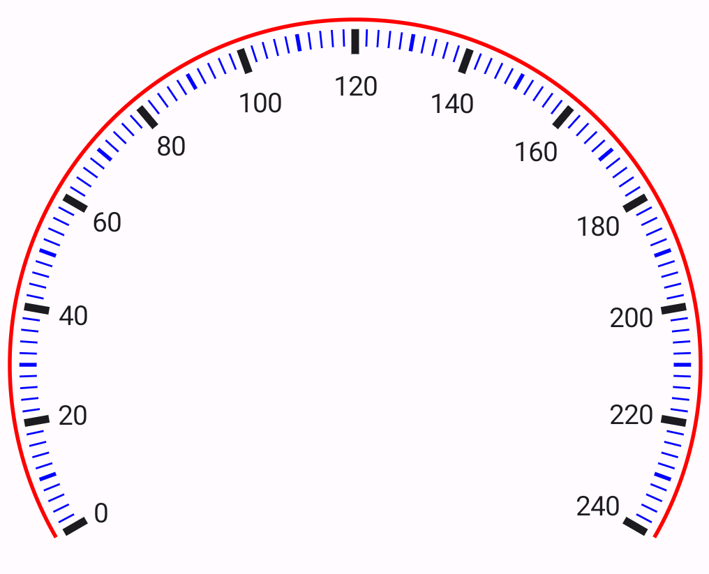
Looks much better now :)
Drawing the Speed Indicator
The only thing left now is the speed indicator. Similar to the speed markers, the indicator is a simple line. Its starting point is the center of the arc, and its ending point is determined by the current speed’s position on the arc. We can use the pointOnCircle method to obtain the starting and ending points for the indicator.
1
2
3
4
5
6
7
8
9
10
11
12
13
14
15
16
17
18
19
private fun DrawScope.speedIndicator(
    speedAngle: Float
) {
    val endOffset = pointOnCircle(
        thetaInDegrees = speedAngle.toDouble(),
        radius = size.height / 2 - INDICATOR_LENGTH.toPx(),
        cX = center.x,
        cY = center.y
    )

    drawLine(
        color = Color.Magenta,
        start = center,
        end = endOffset,
        strokeWidth = 6.dp.toPx(),
        cap = StrokeCap.Round,
        alpha = 0.5f
    )
}
That’s it. We now have our speedometer.
We can also accept the speed value as a user input to animate the indicator and bring our speedometer to life:
Weekend project: Building a speedometer in Jetpack Compose. Aligning the text was the biggest challenge. Blog soon!#AndroidDev #JetpackCompose pic.twitter.com/Gx80RbklLX
— Saurabh Arora (@iSaurabhArora) July 23, 2023
The full code for this (along with animation and seekbar for demo) can be found at:
https://gist.github.com/saurabharora90/636ca81907e20997199795ca16368276